Easy Cash $$$ Do a simple CAD Design for 3D Printing - 31/03/2020 15:48 EDT

  • ステータス: Closed
  • 賞金: €100
  • 受け取ったエントリー: 31
  • 優勝者: sami3008

コンテスト概要

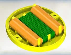
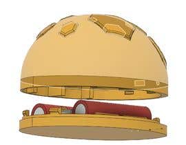
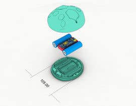
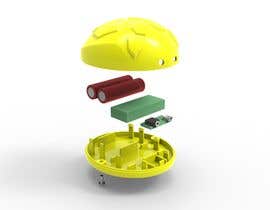
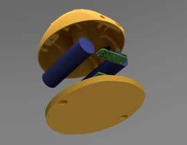
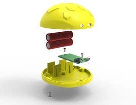
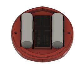
Design a simple circuit board holder and battery holder to be 3D printed with the base.
The circuit board is L= 64 mm * W= 27 mm * H= 12 mm
There will be connected wires on the top of the circuit board
We have two batteries each with the dimensions below:
The battery’s dimensions are L=67 mm * D = 20 mm.
Where L is length, W is the width H is the Height and D is the diameter respectively.

I have included 2 mm on each side in the dimensions for perfect fit.


Bonus Point the minimalistic design.
Bonus Points if the Circuit Board and batteries can be secure in place
Bonus Point is the design does not take too much space
Bonus point if the overall design does not use too much materials

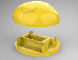
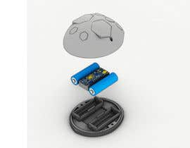
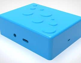
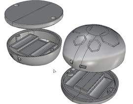
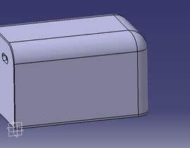
Included is also the design of the Top case.
Bonus Points if you can improve on this design.
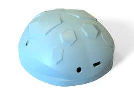
On the front of the Top case is the holes for the mini USB and a female audio jack.

The diameter of the female audio jack hole is 6 mm. The distance from the perimeter of the female audio jack to the perimeter of the hole of the mini USB is 14 mm.
The diameter of the mini USB hole is 10 mm * 4 mm

I want a CAD and 3D printing designer to join my team.

Note:
The overall Case design I have shared with you is 15 percent larger than required.

Please refer to images and designs.

推奨スキル

採用者フィードバック

“Patient, enjoys learning and very engaged. Mohamed provided me with very detailed and high quality feedback throughout the project. The results were everything I could have asked for... Thank very much Mohamed.”

プロフィール画像 IcoNNZ, Ireland.

このコンテストのトップエントリー

エントリーをもっと表示

公開説明ボード

  • jnpulkit
    jnpulkit
    • 4年間前

    Requesting update from the Contest Holder

    • 4年間前
  • mridulmaheshwari
    mridulmaheshwari
    • 4年間前

    Can't able to submit entry. Please, submit option is unavailable.

    • 4年間前
  • mridulmaheshwari
    mridulmaheshwari
    • 4年間前

    wait for some time sir, will be posting an improved design shortly. The site is not running properly in india.

    • 4年間前
  • tricker3006
    tricker3006
    • 4年間前

    please check #43

    • 4年間前
  • DC47
    DC47
    • 4年間前

    Please Check #36

    • 4年間前
  • IcoNNZ
    コンテスト所有者
    • 4年間前

    #23 Very lovely minimalistic design... But you can still remove more waste material from the base. Also The board I mentioned is not the board that will have the mini usb port and audio jack...

    • 4年間前
    1. jnpulkit
      jnpulkit
      • 4年間前

      Hi,
      I have updated the design. Please check #32

      • 4年間前
  • mridulmaheshwari
    mridulmaheshwari
    • 4年間前

    please check #31

    • 4年間前
  • dedierwanto2686
    dedierwanto2686
    • 4年間前

    Please check #30 ,waiting your feedback ,thanks

    • 4年間前
  • IcoNNZ
    コンテスト所有者
    • 4年間前

    #10 Your design has over hanging structure this won't print well without support structure

    • 4年間前
    1. RKTechCanada
      RKTechCanada
      • 4年間前

      Not sure where you are referring to..
      This design is no more difficult than the dome you had printed for yourself already,
      what splicing software and printer are you using so i can tailor the design to any limitations you may have?

      Outstanding Questions:
      What are the available contact points for the PCB we are designing for?
      Can we have a photo of the PCB?
      How are you connecting to the batteries?
      Are there contacts mounted in the printed frame (like in a TV remote) or will the batteries soldered?

      • 4年間前
    2. IcoNNZ
      コンテスト所有者
      • 4年間前

      If you read my previous comments you will understand... For now assume that there will be an additional small PCB housing the audio jack and mini USB port. The batteries are soldered. The over hand in your design is in the shell...

      • 4年間前
  • IcoNNZ
    コンテスト所有者
    • 4年間前

    #28 please read comments below

    • 4年間前
  • IcoNNZ
    コンテスト所有者
    • 4年間前

    #29 This design is nice but it's wasting too much space... I do not want any additional screws... Also the circuit board does not have an audio jack and mini USB... For now assume that the USB port and Audio jack are stand alone component or on a smaller different board...

    • 4年間前
  • MKafri
    MKafri
    • 4年間前

    Please check #28

    • 4年間前
  • IcoNNZ
    コンテスト所有者
    • 4年間前

    #20 love your design, you removed a lot of waste material, which is what I want... But the batteries are not supported properly

    • 4年間前
    1. MATIASB005
      MATIASB005
      • 4年間前

      The image is not well appreciated, but small towers on the sides function as a clip for the battery.

      • 4年間前
  • IcoNNZ
    コンテスト所有者
    • 4年間前

    #27 This design is lovely simple yet aims to archive the objective. Your clamp like structure seem too small to keep the battery in place.

    • 4年間前
  • IcoNNZ
    コンテスト所有者
    • 4年間前

    #25 You have an over hanging structure

    • 4年間前
  • IcoNNZ
    コンテスト所有者
    • 4年間前

    #24 please read some feedback that I shared here

    • 4年間前
  • IcoNNZ
    コンテスト所有者
    • 4年間前

    #21 I like how clean and professional your design looks... I like how there are no screws or additional parts that need to be printed separately. There are no over hanging structures and you have reduced a lot of the materials. Make the support structures for the batteries to be strong enough... Submit the rest of the Design for feedback...I think you can still reduce a little more materials waste...

    • 4年間前
  • IcoNNZ
    コンテスト所有者
    • 4年間前

    #18 #19 I don't want screws...

    • 4年間前
  • IcoNNZ
    コンテスト所有者
    • 4年間前

    #22 I like your design... But the circuit board holder is an over hanging structure and will not print well

    • 4年間前
    1. IcoNNZ
      コンテスト所有者
      • 4年間前

      Also you can still remove more waste from the base

      • 4年間前
  • IcoNNZ
    コンテスト所有者
    • 4年間前

    #13 Very good visualization and use of color I could clearly see all the parts. I liked how you labeled the. Just one problem you used way too many parts... and I don't want to use more screws in the design

    • 4年間前
    1. MKafri
      MKafri
      • 4年間前

      Thank you for your feedback, please wait my entry.

      • 4年間前
  • prasadpvc92
    prasadpvc92
    • 4年間前

    Hello CH, kindly initiate message/chat regarding improvements done to #4 and #16 .
    Improved design is ready using only the 2 base and top pieces.

    • 4年間前
  • mridulmaheshwari
    mridulmaheshwari
    • 4年間前

    #extended #extended please , taking time

    • 4年間前
  • lecorbusier1234
    lecorbusier1234
    • 4年間前

    hi CH, please tell me what do you think about my design #17 ?

    • 4年間前
  • jnpulkit
    jnpulkit
    • 4年間前

    Hi,
    Assuming that there are no holes in the PCB. I would really appreciate if you could please send a layout/footprint of the same so that i may arrange the components properly.
    Also, after correcting for the 15% increased size that you have shared (by scaling down the entire model to 86.95%), the components fit snug in the base. Hope you have considered manufacturing tolerances in your original design dimensions.

    • 4年間前
    1. jnpulkit
      jnpulkit
      • 4年間前

      To add to this, since you are going to screw the two pieces from the bottom, I think you can keep the screw hole limited to 80% of the current distance. This way your upper cover will look aesthetically more pleasing (without a hole) and you can add threaded portion using threaded inserts in this.
      Also, I assume you will require tooling and mold design for manufacturing it after your prototyping is completed. I would design this for manufacture so that your prototype and final product are not far from each other.

      • 4年間前
  • IcoNNZ
    コンテスト所有者
    • 4年間前

    #16 Nice design but I don't want the design to have more that 2 part to prints. The parts are the base and the top. It's nice that you got the measurement for the mini USB and Audio jack hole right... Really glad to see that... Make your design minimalistic in materials

    • 4年間前
    1. mridulmaheshwari
      mridulmaheshwari
      • 4年間前

      Please don't close early , wait for my design , will be posting soon.

      • 4年間前
    2. prasadpvc92
      prasadpvc92
      • 4年間前

      Dear Contest Holder, kindly initiate chat to discuss details regarding the batteries.
      Will implement all your suggestions provided in these comments which were not provided initially in the brief.

      • 4年間前
  • DC47
    DC47
    • 4年間前

    please send PCB photo

    • 4年間前
  • IcoNNZ
    コンテスト所有者
    • 4年間前

    #14 I do not want to 3D print any additional parts, apart form the base and the top shell.

    • 4年間前
    1. IcoNNZ
      コンテスト所有者
      • 4年間前

      The center of the audio jack should be 10 mm from the center line that separates the right side of the shell from the left side... You have this wrong in your design. Also perimeter of the mini USB hole should be 7 mm from the center line. This is also wrong in your design.

      • 4年間前
    2. NipunVitharana
      NipunVitharana
      • 4年間前

      Well noted, can you initiate a chat so I can incorporate the comments. So, you can comment until the design fits you well. I will show you the sketches and dimensions of sketches in the model itself in real time video

      • 4年間前
  • IcoNNZ
    コンテスト所有者
    • 4年間前

    #9 You have completely changed the design when I told you not to... I don't want more screws... Your design uses way too much materials...

    • 4年間前
  • IcoNNZ
    コンテスト所有者
    • 4年間前

    #17 I like how your design looks very simplistic, you did not change much... You did not use screws in your design and very thing seems to come together nicely in your design. Did you make any extra parts? I did not see any extra parts... Please submit more images of different angle so I can see better. Also I like the use of color in your design for better visualization.

    • 4年間前
    1. IcoNNZ
      コンテスト所有者
      • 4年間前

      Just one thing to note the base will also be 3D printed so the over hanging structure that slips to secure the board will not print well. Hope you can fix that

      • 4年間前
  • IcoNNZ
    コンテスト所有者
    • 4年間前

    #12 I like how your design used less material... But I did not like that there is an extra part that must be 3D printed separately and screwed in place to hold the board and batteries in place...

    • 4年間前
    1. IcoNNZ
      コンテスト所有者
      • 4年間前

      Also when reducing materials make sure not to compromise the strength on the base

      • 4年間前
  • MKafri
    MKafri
    • 4年間前

    Hi, Please check #13

    • 4年間前
  • dedierwanto2686
    dedierwanto2686
    • 4年間前

    Hi CH,can you send file STEP or IGES?

    • 4年間前
  • dedierwanto2686
    dedierwanto2686
    • 4年間前

    Hi CH,please wait until contest end...work on it

    • 4年間前
  • IcoNNZ
    コンテスト所有者
    • 4年間前

    #7 Excellent use of space... I like how the entire design consist of just two pieces, this is closer to what we are looking for. The batteries are rechargeable and will not need replacing.

    • 4年間前
    1. IcoNNZ
      コンテスト所有者
      • 4年間前

      The circuit board holder design is great but will no be feasible as it will get in the way as there are component on the edge of the circuit board.

      • 4年間前
    2. RKTechCanada
      RKTechCanada
      • 4年間前

      May we please see a photo of the PCB to better understand the spacing limitations or a more descript write up to optimize the design. Thank you

      • 4年間前

コメントをもっと見る

コンテストの開始方法

  • あなたのコンテストを投稿

    あなたのコンテストを投稿 速くて簡単

  • たくさんのエントリーを集めましょう

    たくさんのエントリーを集めましょう 世界中から

  • ベストエントリーをアワード

    ベストエントリーをアワード ファイルをダウンロード - 簡単!

コンテストを今すぐ投稿 または本日参加!